PORTFOLIO//FIRST PLACE · 2012
Low Cost
3D Mapping
This is where the computer vision work on this site starts. Detection, extraction and vision in production all run on the geometry learned here.
A final-year project in the Department of Electrical, Electronic and Computer Engineering at the University of Pretoria: a 3D scanner made from a projector, a webcam, and a turntable I specified, built and wrote the firmware for. Gray-coded patterns go onto the object, line-plane intersection turns every decoded pixel into a depth, and eighteen scans taken 20° apart merge into one textured model.
Three months, and it runs the whole stack: stepper selection and PIC32 firmware at one end, ICP registration, Marching Cubes and Taubin smoothing at the other. It also has a measured failure in the middle that was never fixed, and that is on this page too.
CAPTURE TO MODEL/
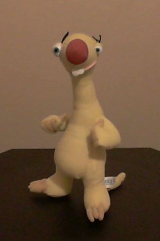
The object
Fig 35 · p.49A soft toy on the turntable platform. Rigid enough to hold its shape, matte enough to take a projected pattern.
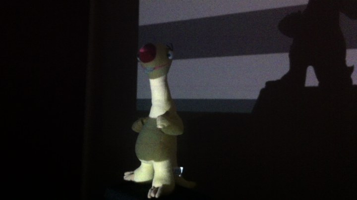
Capture
ORIGINAL FOOTAGEThe rig running. Gray-coded patterns step from coarse to fine across the object and the webcam reads each one back; line-plane intersection then gives every decoded pixel a depth.
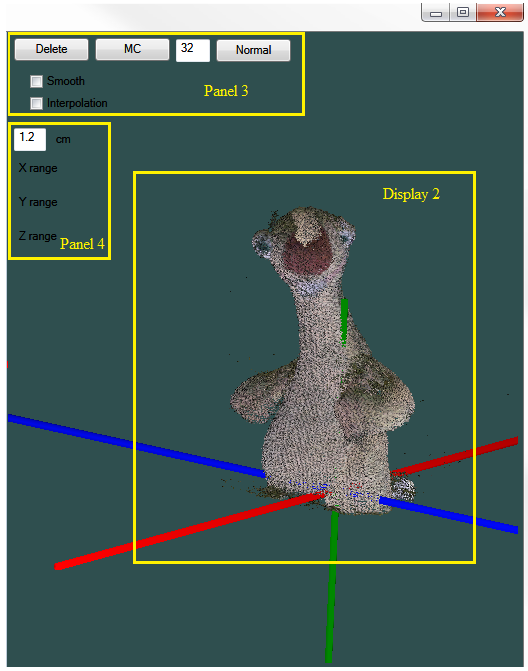
Point cloud
Fig 33 · p.43One view, thresholded against a background scan and rendered in the WPF viewer. Over a hundred thousand points from a single exposure.
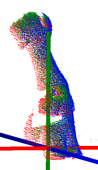
Pairwise registration
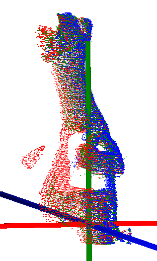
Fig 39 · p.52Three clouds, colour-coded, merged by ICP. Left: a good initial alignment. Right: the same scans seeded from the rotation axis instead. Same data, converging much tighter.
Surface & texture
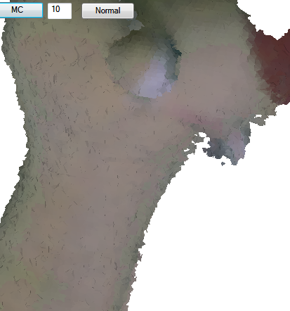
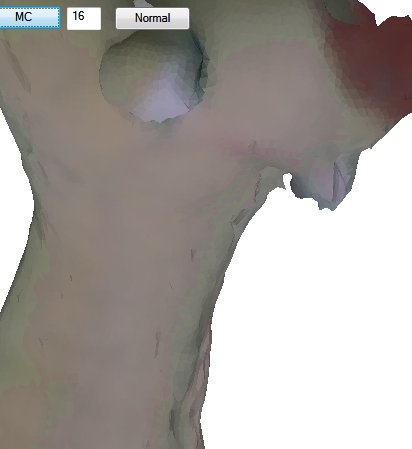
Fig 43 · p.57Marching Cubes over the merged cloud, then Taubin smoothing. Left: the raw isosurface at MC 10. Right: smoothed at MC 16, with per-face colour averaged from the points it was cut from.
0.7mm
About the thickness of a credit card
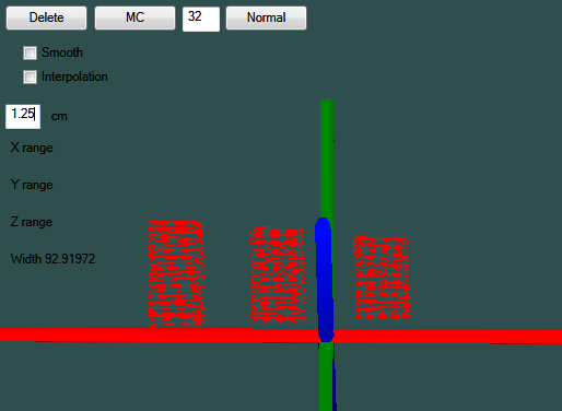
Three cardboard markers set 2.00 cm apart, measured back off the point cloud. Across all five trials it averages 1.0 mm, and the worst single reading in the set is 3 mm.
That is the figure the whole rig stands on. Every scan after it inherits it, so a single view being accurate is what makes a merged model worth measuring at all.
MEASURED/
| Scan (cm) | 1 → 2 (cm) | 2 → 3 (cm) | 2 behind 1 (cm) | 3 behind 2 (cm) | Mean dev. (mm) | Rel. (%) |
|---|---|---|---|---|---|---|
| 1† | 1.92 | 1.94 | 1.92 | 1.94 | 0.7 | 3.5 |
| 2 | 1.87 | 1.88 | 1.91 | 1.95 | 1.0 | 4.9 |
| 3 | 1.96 | 1.98 | 1.84 | 1.93 | 0.7 | 3.6 |
| 4 | 1.94 | 1.96 | 1.70 | 1.80 | 1.5 | 7.5 |
| 5 | 1.96 | 1.84 | 1.79 | 1.93 | 1.2 | 6.0 |
| All | five trials, twenty gaps | 1.0 | 5.1 | |||
Four gaps per scan, each 2.00 cm by tape measure, read back off the point cloud. Deviation and relative error are computed from those measurements against the 2.00 cm truth. † Scanned inside the calibrated focus area; the remaining four were positioned randomly around it, which is what the spread in the last two columns is measuring.
THE INSIGHT/
ICP needs a decent starting pose or it settles into a local minimum, and every cloud merged after it is then wrong. Rather than have an operator align each scan by hand, a 1.25 cm square pin stands at the centre of the platform and is scanned once. Its orientation gives the rotation axis; that corrects the camera tilt out of every cloud and lets each new scan be seeded with the rotation the turntable has just made, a known 20°.
0.40 cm0.16 cm60% better
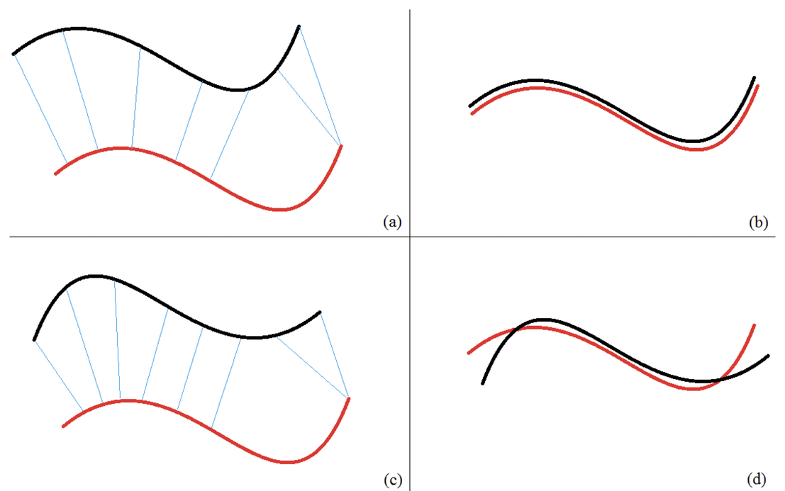
Average misalignment across seventeen pairwise registrations, first full scan against second. §3.4.2.2
THE FAILURE/
Merging eighteen clouds in sequence accumulates error, so the first and the last no longer meet: a 1.33 cm seam, and a sea-shell fold where they overlap. Global relaxation was meant to redistribute that error across every cloud and close it. Over five iterations it did not converge:
1.330.962.031.092.41cm
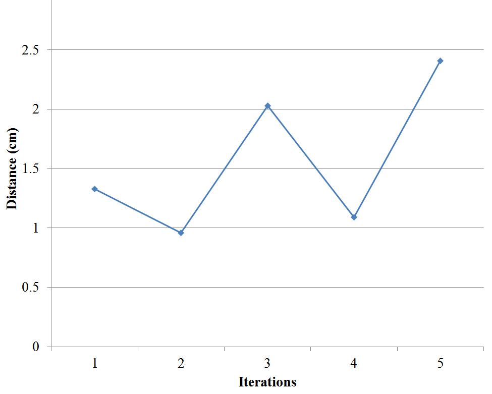
Diagnosed in the report itself: the error was spread evenly across the merged clouds instead of weighted. The fix was identified too late in the timeline to re-run the results. §4.2
BUILD/
Projector and webcam, both at least 800×600, calibrated with ProCamCalib. Gray coding rather than phase shift: flood-fill phase assignment gives no unique row or column identity, so line-plane intersection has nothing to key against.
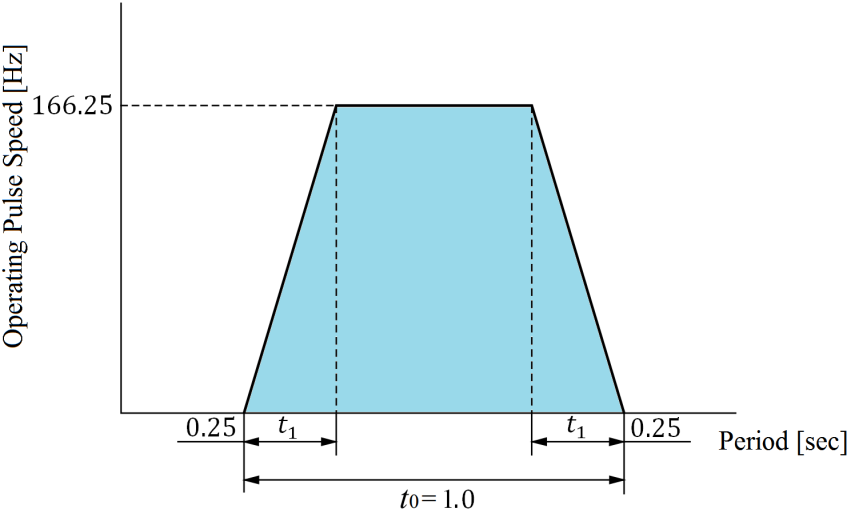
PMG4250 geared bipolar stepper, 0.15° resolution at ±7%, driven by an A4988 and a PIC32MX320F032H over RS-232 through a MAX3232. 133 steps lands 19.95° against a 20° target at 166.25 Hz; 2.5 kg·cm required at a safety factor of 2, against 10 kg·cm available. Carries 4 kg.
C#, OpenCV 2.4 and WPF. ICP over Canny critical points, nearest neighbours through a KD-tree, non-overlapping points trimmed to remove alignment bias. Marching Cubes then Taubin smoothing: vertex-to-cloud distance falls 0.122 → 0.065 cm as the sampling cube goes 43 → 13 mm, and smoothing improves it at every size without shrinking the model.
Transparent and reflective surfaces, ambient light, an over-exposed camera, a mis-calibration, or a centre pin out of focus. Marching Cubes ambiguity leaves occasional holes in the mesh. Anything past 30 × 30 × 30 cm runs out of memory: WPF degrades near a million points and eighteen scans clear a hundred thousand each.
Every figure and measurement on this page is reproduced from Low Cost 3D Mapping using Structured Light, M. Vosloo, Department of Electrical, Electronic and Computer Engineering, University of Pretoria, project EPR400, November 2012. The capture footage in stage 02 is from the original build rather than the report. Scope, stated plainly: the Gray-code decode is a port of Lanman & Taubin’s cvStructuredLight from C++/OpenCV 1.1 to C#/OpenCV 2.4, disclosed in the report’s own engineering change proposal. Everything else was built from first principles: the initial-alignment method, ICP, global relaxation, Marching Cubes, Taubin smoothing, texturing, artefact removal, and the whole turntable from motor selection through firmware and housing. The project took first place for Computer Engineering in the final-year project competition and exhibition, and was invited for poster presentation at PRASA, the Pattern Recognition Association of South Africa.